Stuart Lansburg and Christophe Jehoulet
Saft
The changing needs of data center developers and operators, combined with the explosion in cloud computing, are driving the demand for high density storage and secure online operations. There are more than half a million data centers in existence today. All together, they suffer 2.8 million hours of downtime each year at a cost of $426 billion. Implementing a high power UPS can reduce significantly this downtime and its associated costs. Energy storage based on high power Li-ion (lithium-ion) battery systems is now emerging as an efficient alternative to traditional lead-acid batteries. This article outlines the specific benefits of Li-ion technology for data center UPS installations and explains how Saft has incorporated them in a new modular system designed for installation in a stand-alone 19-inch rack-mountable format.
Li-Ion Advantages
Large format industrial Li-ion cells provide both high power capability and high energy density and are also maintenance-free. When Li-ion cells are integrated into systems with electronics that provide redundant safety features, operating features for optimized performance and communication features for application interaction/control, then the overall package is perfectly suited to ensure the high uptime required by data centers.
Li-ion battery systems are both light in weight and compact, offering a small installation footprint that allows operators to free up space for other important data center functions. They also provide a long, reliable, maintenance-free and safe operating life that minimizes downtime costs and total cost of ownership (TCO).
Saft has more than 15 years of experience in designing, testing and producing Li-ion systems across a wide range of industrial applications. This has now been incorporated in the Intensium Flex system developed specifically for data center UPS or high voltage DC architecture (HVDC).
Li-Ion System Approach
Traditionally, the terms ‘batteries’ or ‘battery packs’ has been used to describe a string of lead-acid or nickel-based cells connected electrically in series. Usually, they incorporate minimal electronics, such as a current interrupting device (i.e. a fuse). In contrast, when working with Li-ion technology, the cells are only one part of a global system that also includes a fuse added as a redundant safety feature, electronic functions such as monitoring and cell balancing, processors with control algorithms, electrically operated contactors and the ability for bi-directional communication. Therefore, when discussing Li-ion systems with these added functionalities, we refer to modules, rather than batteries or battery packs, to designate the various sub-units.
The Intensium Flex system comprises three main modules:
• The Synerion module (with Li-ion cells)
• The BMM (Battery Management Module)
• The MBMM (Master Battery Management Module)
When these standard building blocks are assembled together, they enable a UPS or HVDC Li-ion system to be customized to suit voltages from 48 V to 860 V.
The Synerion Module
The Synerion module incorporates 14 Li-ion cells and their associated electronics in a 3 RU unit that is 19-inch rack mountable and provides a nominal 48 V.
Two different Li-ion cell designs are used according to the application. One is a high power cell for applications requiring up to 15 minutes of autonomy and the second is a medium power cell suited for more than 15 minutes of autonomy. Like traditional batteries, with Li-ion, there is a trade-off between capacity and power when optimizing cell design.
The NCA electrochemistry selected for Saft Li-ion cells in industrial standby and renewable energy storage sector applications represents a trade-off between inherent electrochemical safety and superior lifetime performance. The overall safety level of the module is not compromised, however. Redundant safety features are included in the electronics and the cell, starting with the controlled venting feature inside each cell.
A modular electronic board called the System Monitoring Unit (SMU) is connected to the cells in a Synerion module. It interconnects the cells and provides monitoring and control functions such as voltage balancing and the detection of the end of charge voltage, end of discharge voltage, an over-temperature condition and under/over safety threshold voltage limit. This information is transmitted over the internal CAN bus to the BMM, which acts as the prime safety control unit.
The module, used either as a single module (48 V) or connected in series with several other modules, cannot ever operate alone. It must be connected and managed by a BMM. Systems up to 864 V nominal can be created.
The BMM (Battery Management Module)
The BMM module is the brain of the Intensium Flex system that interconnects the power and the communication circuits with the application. This allows it to interrupt the string current (condition when a safety threshold is exceeded) and to communicate between the SMU circuits and the application. Its functions include current measurement, CAN bus and dry contactor signal (potential free contactor) communications, electromechanical contactor control (built-in) and processing of monitored data from the SMU. It provides the first level of safety protection using the primary thresholds (voltage, current and temperature) written in the safety algorithms.
Up to 18 Synerion modules (48 V configuration) can be connected and managed by one BMM. The self-powered feature allows all the functionalities to remain active in the case of an AC power blackout.
BMM/Synerion strings can be connected in parallel with other BMM/Synerion strings to provide more power or more energy for the application. To do this, the MBMM is required.
The MBMM (Master Battery Management Module)

The MBMM module provides a ‘super boss’ function. It connects to the communication functions of the BMM/Synerion strings. In this case, the power connections from the BMM are still connected directly to the application bus without physically being routed through the MBMM. Its functions include coordinating start-up on charge and shut-down at the end of discharge. Up to 20 BMMs can be connected to one MBMM. Intensium Flex systems with up to 720 kWh (using Synerion 48M) of energy or up 4.8 MW of power (1 minute autonomy using Synerion 48P) can be configured in this way.
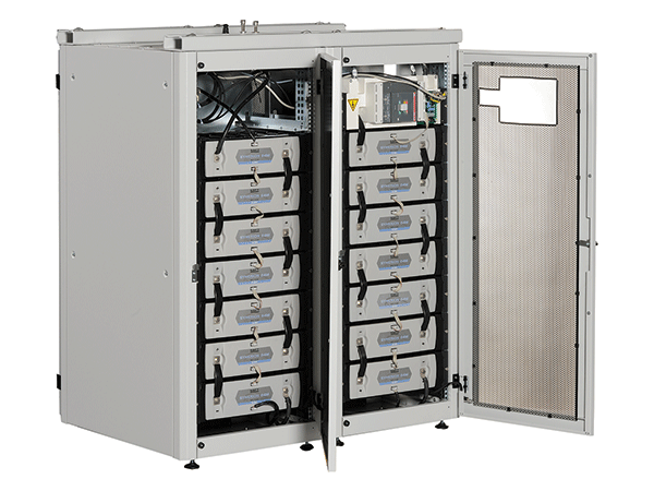
With all the blocks assembled in an Intensium Flex system, an example of data that can be communicated include, its ID, voltage, current, mode of operation, contactor status (open or closed), min./max. cell voltages, min./max. temperature, maximum currents allowed in charge and discharge (IMR for recharge or IMD for discharge), state of charge (0 percent to 100 percent), state of health (0 percent to 100 percent), alarm status and internal watchdog function (for proper functioning of BMM/MBMM). With these standard building blocks, a system can be customized. Figure 1 shows a system configured for 672 V nominal. It uses 14 Synerion 48M connected in series with one BMM. It has a rated energy (C/5) of 28 kWh. The rack height is approximately 25 RU.
Discharging
The maximum delivered power is limited by either the current capability of the cell’s electrochemistry (defined by the threshold variable IMD) or the connecting hardware/components in the Synerion module and the BMM. For the shortest autonomy, the connecting hardware/components limit the Synerion module performance. In addition, in the case of paralleled BMM/Synerion strings, the normal variations in string resistance and manufactured cell capacities requires that the single string performance be derated by approximately 10 percent for discharge autonomies less than five minutes.
Charging
The recharge of the system is by a constant current/constant voltage (CC/CV) method. The single set point voltage should be equivalent to 4 V per cell or 56 V per module. In that case, 100 percent state of charge (SOC) is obtained. The maximum obtained SOC is a function of this set point voltage. The general rule of thumb is that the SOC will be approximately 10 percent less for each 1 V per module less than 56 V. The available performance on discharge is reduced. The module is considered as fully charged anytime the current decreases to less than 1 A during the CV phase. The recharge current level during the CC phase is limited by the value of the maximum allowed normal charge current (IMR). This value is a function of the module temperature (Tm), module SOC and the cell type that is used. The IMR value is defined to make sure of safe cell operation and to avoid pre-mature cell aging (particularly important for frequent cycling applications).
Two IMR values are defined for each state (Tm, SOC and cell type); an IMR pulse and an IMR continuous. The IMR continuous is the maximum allowed current while continuously charging and it is approximately equal to 1.0 to 2.0 times the C5 Ah at 25°C (depending on cell). The IMR pulse is the maximum allowed current for a maximum of 5 seconds and it is approximately 3 times the IMR continuous value. If ever the recharge current available from the application exceeds the IMR pulse for more than five seconds, the contactor in the BMM will be opened to limit the system to a safe operation mode.
As an example, with a C/2 re-charge rate and 56 V per module set point voltage, the Intensium Flex will recharge fully in less than 2.5 hours from a full discharged state.
The recharge efficiency is close to 100 percent columbic (Ah efficiency) and it is independent of recharge rate, temperature and percent-SOC.
Service Life
Service life depends on calendar time usage and the cyclic duty usage. As it ages in use, the available capacity decreases and its internal resistance increases. Both mechanisms are irreversible. For life estimations, the calendar aging and cyclic aging are considered separately when discussing factors that affect each. For the end of life, it is commonly considered that 20 percent loss of capacity and approximately two-times higher internal resistance represents end of life. The factors that impact the calendar aging are the percent-SOC and the module temperature. The factors that impact the cyclic aging are the level of recharge current (percent of Ic max.) and depth of discharge.

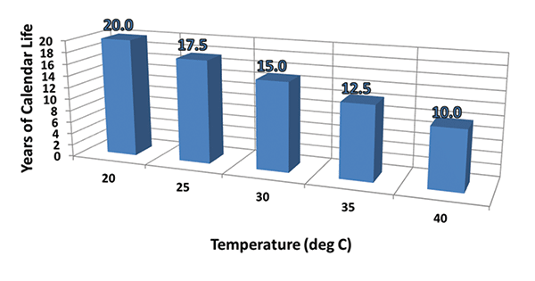
Calendar aging is the normal case in data centers, since the AC grid offers a high uptime that avoids the need to frequently cycle the energy storage system. It follows that the main factors when considering the service life are the calendar life factors; namely the percent-SOC and the temperature. Figure 2 shows the expected service life as a function of temperature under the worst case percent-SOC of 100 percent. The impact of cycling life factors may become more significant if the cycling duty calls for full discharge and re-charge cycles every seven days or less.
Integrating into Practical Applications
The Intensium Flex system can be integrated within existing data center infrastructure, where it requires about one quarter of the space and about one half of the installed energy to do the same job. It can also allow co-location next to existing equipment (depending on local building codes) since the weight of the system can be as low as 10 percent of the weight of existing battery technologies. This suggests that no special infrastructure reinforcements need to be considered when placing the system.
Furthermore, the system gives the added benefit of communication with the application. The system indicates its status (alarms active, SOC, voltage, current, operating mode), informs the operator of the maximum allowed recharge current (IMR) to allow output current control, inform them of the maximum allowed discharge current (IMD) to let them know if they will outgrow its autonomy capabilities and finally tell the operator when it has reached the end of its life.
Sizing Comparison
The advantages of system are especially apparent when compared to the sizing of a traditional solution like a large VRLA (valve regulated lead-acid) battery. If we assume application equipment that operates with a 480 V battery and a battery load is 160 kWbatt (180 KVA UPS with η = 0.90 and Cosφ = 0.80), in order to provide backup time of 10 minutes, an Intensium Flex 2 x 480 10.48P is needed. In other words, two parallel connected strings of 10 by 48P Synerion modules connected in series should be connected to the output bus to provide a 480 V system utilizing 2 BMMs and one MBMM. This would call for the installation of two 19-inch equipment cabinets with 37 RU of height and 450 mm of depth. This would be equivalent to 28 kWh of energy in order to support a (160 kW) by (10 minutes) = 26.6 kWh load requirement.
Summary
New module systems are well adapted for data center applications. The modular design approach allows it to be adapted for voltage needs between 48 V to 864 V nominal. In addition, its Li-ion technology offers a significant saving in footprint and weight, which allows the possibility to co-locate the system with existing equipment (depending on local building codes) or free up space for other data center needs. While in service, the system offers advanced communication and control features for optimized operation and performs with high power density, fast and efficient recharge and improved lifetime when compared to traditional solutions.
For more information, please visit www.saftbatteries.com.


