
Mary Anne Tupta
Keithley Instruments, a Tektronix Company
Rechargeable batteries power a rapidly expanding range of electronic devices, from laptops and tablets to mobile phones and wearable health-monitoring devices. When purchasing these devices, consumers typically take a hard look at battery life and recharge times; operating time is often a deciding factor in the purchase of a mobile device. As a result, researchers are studying ways to increase battery life and decrease the cost of rechargeable batteries.
Researchers commonly perform charge/discharge cycling when characterizing rechargeable batteries. During development, charge/discharge cycling gives researchers information about the battery, such as its internal chemistry, capacity, number of usable cycles and lifetime. In production testing, a discharge/charge cycle is often performed to verify battery specifications and screen out defective products.
A typical battery discharge/charge test configuration often includes a programmable power supply, an electronic load, an electronic switch, a voltmeter and an ammeter. Significant configuration time is required to synchronize all these instruments into a working test station. Another option is to use a potentiostat or galvanostat, which are popular instruments used for electrochemical studies. However, there may be disadvantages to using either of these instruments, including the limited control users may have over them.
SMU Instruments Simplify Battery Charge/Discharge Testing
Source measure unit (SMU) instruments offer a simpler approach to battery charge/discharge cycling. These instruments offer voltage and current sourcing and measurement ranges that are well suited for this application. An SMU instrument can either charge a battery by setting a desired current rate or discharge a battery by dissipating power, while monitoring a battery’s voltage. A single SMU instrument can also replace an entire rack of equipment, minimizing equipment and integration costs.
For both the charge and discharge cycles, the SMU would be configured to source voltage and measure current. Figure 1 is a simplified circuit diagram of both the charge and discharge cycles.
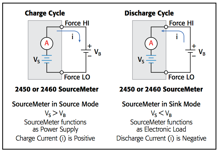
A battery is normally charged with a constant current. To do this with an SMU instrument, the voltage source is set to the voltage rating of the battery and the current limit of the source is set to the desired charging current. At the start of the charging cycle, the battery voltage will be less than the SMU instrument’s voltage output, and current will flow into the battery. Because the current is limited, however, the SMU instrument acts as a constant current source until the battery reaches the programmed voltage level. As the battery becomes fully charged, the current will decrease until it reaches zero or near zero. To minimize safety hazards or battery damage, avoid overcharging the battery.
When discharging a battery, the SMU sinks current because it is dissipating power rather than sourcing it. To draw current from a battery, the voltage source of the SMU instrument should be set to a lower level than the battery voltage and the SMU’s current limit should be set to the desired discharge rate. When the output is enabled, current from the battery will flow into the HI terminal of the SMU instrument. As a result, the current readings will be negative. The discharge current should stay constant until the battery voltage decreases to the voltage source setting of the SMU.
Rates for constant current charging and discharging are determined by the battery’s capacity, which is the amount of electrical charge that the battery can store. The capacity is specified in milliampere-hours (mAh) and should be expressed in terms of a discharge, or load, current. The rate at which the discharge current will discharge the entire battery in one hour is known as the C-rate. For example, a battery rated at 1,000 mAh will output 1,000 mA for one hour if discharged at 1C. If a 500 mAh cell is discharged at 50 mA, then it is discharged at one-tenth the C-rate (0.1C), so it can source 50 mA for 10 hours.
Making Connections to the Battery
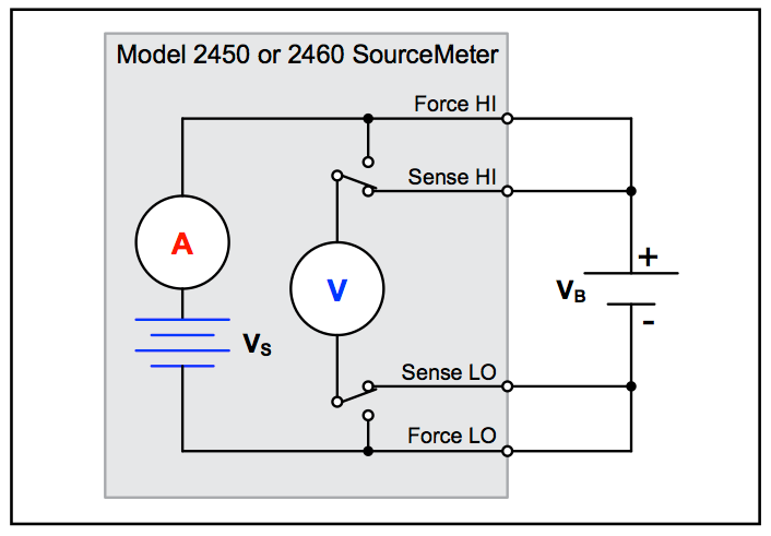
To set up the test, connect the SMU to the battery as shown in Figure 2. Connect the Force HI and Sense HI output terminals of the SMU to the positive (+) terminal of the battery and the Sense LO and Force LO outputs to the negative (–) terminal of the battery. This four-wire or remote sense connection eliminates the effects of the lead resistance, and improves the accuracy of the battery voltage because the sense connections are made as close as possible to its terminals.
When the output of the SMU is turned off, be sure it is set to the High Impedance (High Z) Output Off State. On this setting, the SMU’s output relay opens when the output is turned off. This will prevent the battery from draining while the output is off.
Automating the Discharge Cycle
Charge and discharge cycling often takes several hours, so automating the test is important. That’s why it’s important to choose an SMU that includes one or more communication interfaces, such as GPIB, USB and Ethernet, and provides instrument programming support. Automatically charging and discharging batteries requires programming the SMU to perform these steps:
1. Set the SMU to make a four-wire measurement.
2. Set the SMU to measure current. This will enable monitoring the load current.
3. Set the SMU to use its High Impedance Output Off State. This output off state opens the output relay when the Output is turned off and prevents the battery from draining when the battery is connected with the Output off.
4. Set the SMU to output voltage. Even though the unit will output voltage, it will be operating in constant current mode because it will be in current limit until it reaches the desired voltage. For charging the battery, VSMU > Vbattery. For discharging the battery, VSMU < Vbattery.
5. Turn on the voltage source readback function. This will enable the SMU voltmeter to measure the battery voltage as it is either charging or discharging.
6. Set the current limit (or compliance) to the current level at which the battery is to be charged or discharged. This is the load current of the test.
7. Read back the load current, source readback voltage and the relative time stamp.
8. Monitor and record the battery voltage until it reaches the desired voltage level and stop the test.
Discharging a 2,500 mAh Battery
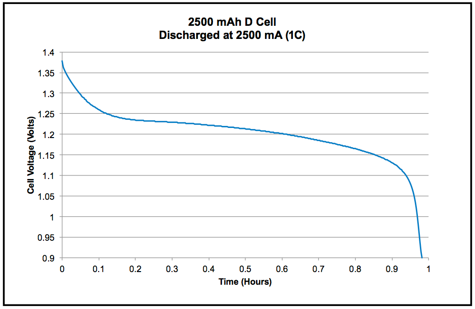
To illustrate how this works, we set up a Model 2460 SourceMeter SMU instrument to discharge a 2,500 mAh D cell (1.2 V) battery. The instrument was programmed as described to perform the steps listed previously (four-wire, source voltage, measure current).
For this particular test, the SMU instrument discharged the battery at a rate of 1C by using a 2.5A load current. Readings of the battery voltage, load current and relative time were taken every ten seconds until the battery voltage reached the specified level, 0.9 V.
The SMU instrument was programmed to execute the test using its embedded Test Script Processor (TSP). TSP technology goes beyond traditional test command sequencers; it fully embeds then executes complete test programs from within the SMU instrument itself. In this case, the instrument was programmed to save all the current, voltage and time readings to a USB drive plugged into the front panel USB port; once stored, the test data can be uploaded to a PC for further analysis. We used the test results to illustrate the discharge characteristics of the 2,500 mAh battery (Figure 3).
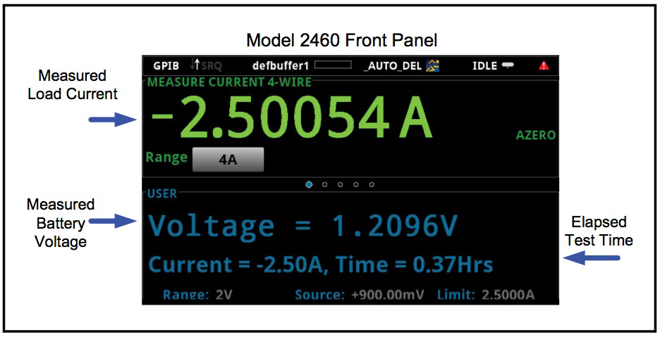
On the Home screen of the SMU instrument, the load current, battery voltage and the elapsed test time can be displayed while the test is in progress (Figure 4). This display makes it simple to monitor the test as it is running and abort it if it isn’t progressing normally. The results can also be plotted in real time on the Graph screen.
Conclusion
SMUs are well suited instruments for performing charge and discharge cycle tests on rechargeable batteries. They can both source and measure both current and voltage accurately at the levels necessary for testing a wide variety of batteries. Their capabilities also allow using a single instrument, which simplifies test setup, reduces programming time and saves rack space.
Mary Anne Tupta is a senior staff applications engineer at Keithley Instruments, Cleveland, Ohio, which is part of the Tektronix test and measurement portfolio. She earned a B.S. in physics/electronic engineering and an M.S. in physics from John Carroll University. She has assisted Keithley customers with instrument applications since 1988.
For more information, please contact Mary Anne Tupta at
mtupta@keithley.com or visit www.keithley.com.