
Commentary contributed by Brian Hammerschmidt, Applications Specialist, Megger
May 2, 2018 | In today’s world, everyone from the automotive industry to the grid energy storage sector are searching for low-cost, sustainable power solutions to meet their ever-changing and increasingly diverse energy needs. Companies are always looking for ways to combine the traditional benefits of lead-acid chemistry with the improved life cycle and power performance characteristics of Li-ion batteries.
Powering the Next-Generation of Batteries
Gridtential Energy, Inc., located in Santa Clara, Calif., manufactures low-cost, high-performance energy storage technologies. They use a patented silicon technology that replaces the lead grid inside a traditional lead battery with a plated silicon wafer that is similar to a solar cell. This increases the battery’s efficiency, energy density, and life cycle.
Collin Mui, lead silicon engineer, of Gridtential Energy, Inc, explained, “Our silicon technology incorporates solar wafer processing techniques into novel bipolar battery architectures while integrating seamlessly into existing battery manufacturing and recycling infrastructures. The result is a high performance, low-cost, quickly scalable technology platform that also eliminates failure mechanisms, extends cycle life and improves power performance at a fundamental level.”
The company, whose main focus is to develop its silicon technology as a drop-in replacement for personal mobility, material handling, and stationary energy storage applications, was recently evaluating several designs of terminal electrical contacts on the battery they offer. They were having difficulty measuring the resistance of the soldered contact in designs. “We did not have an instrument that could measure the low resistance of the soldered joints,” said Mui.
Testing the Resistance of Solder Joints
A low-resistance and manufactured terminal is crucial in the operation of a battery, because poorly-formed terminals cause corrosion, increase impedance, and shorten the life cycle of batteries. “It was important to us to figure out how we could test these batteries,” said Mui. “We could not send our customers substandard products,” he continued.
In today’s world of electronics, increasing demands are placed on all aspects of electrical circuitry. There was a time when the ability to measure 0.01 Ohm was acceptable. In present industrial electronic environments, this no longer holds true, especially in testing these solder joints where acceptable readings are in the low milliohm and micro-ohm range.
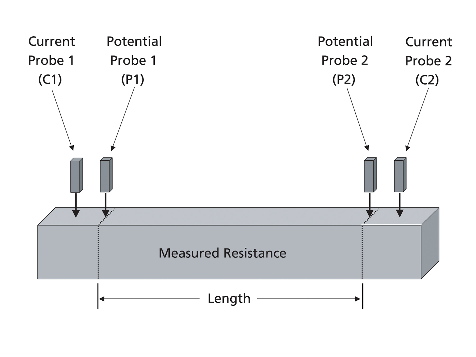
Four wire tests are the most accurate method when measuring circuits below 10 ohms as this method eliminates errors due to lead and contact resistances. This is the test method associated with low resistance ohmmeters. Four wire DC measurements use two current and two potential leads. Four wire DC measurements negate errors caused by the probe lead wire and any contact resistance values in the final reading, ensuring more accurate measurements.
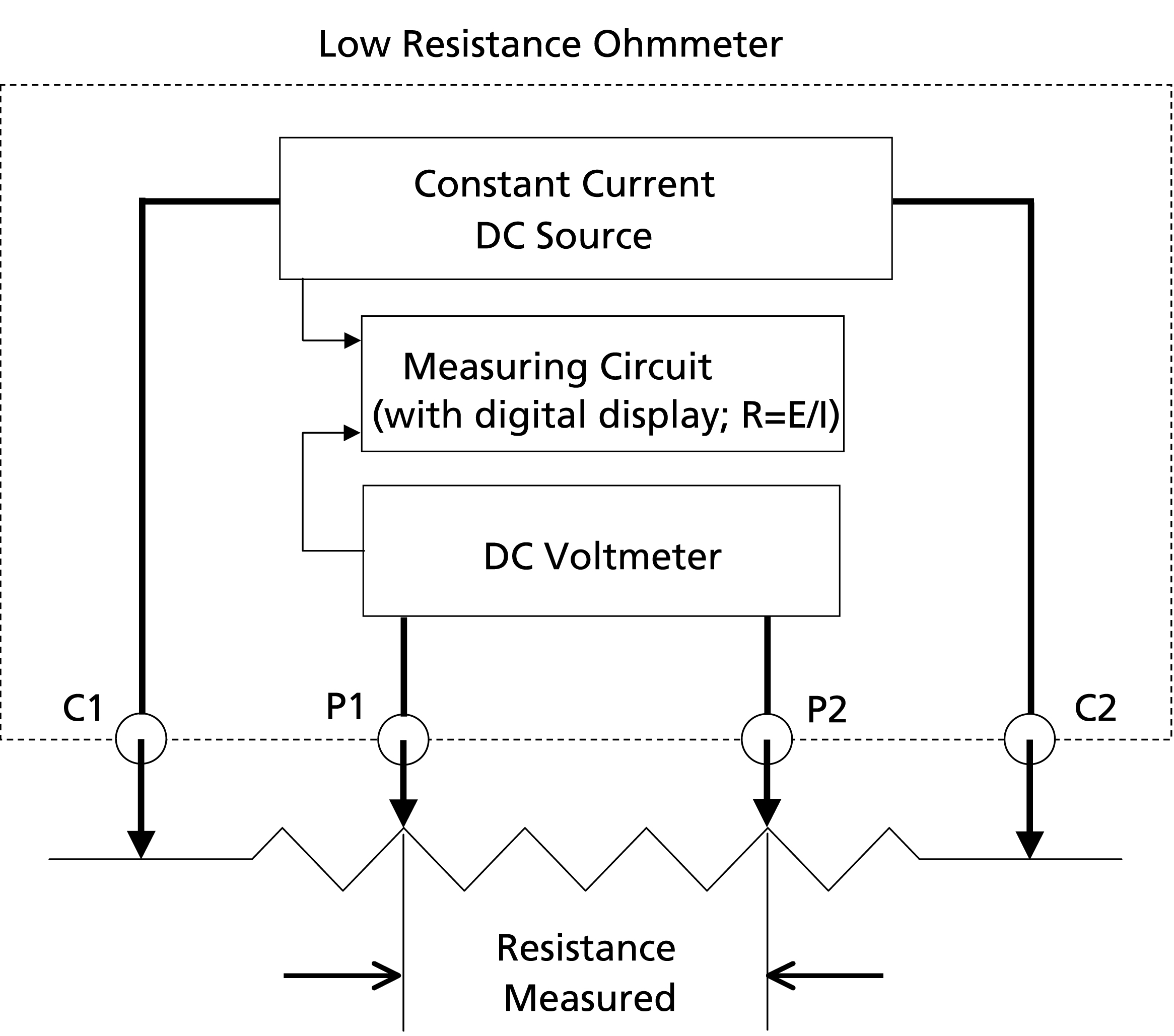
A low resistance ohmmeter uses two internal measuring circuits. The supply injects a current into the test sample through two leads, usually identified as C1 and C2, and the magnitude of the current is measured. Concurrently, two probes (normally referred to as P1 and P2) measure the potential across the sample. The instrument then does an internal calculation to determine the resistance of the test sample.
Current is injected into the item under test via leads C1 and C2. The current that flows will be dependent upon the total resistance of this loop and the power available to push the current through that resistance. Since this current is measured, and the measured value is used in subsequent calculations, the loop resistance, including the contact resistance of the C1 and C2 contacts and the lead resistance of C1 and C2, does not have an effect on the final result.
From Ohm’s Law, if we pass a current through a resistance we will generate a voltage across the resistance. This voltage is detected by the P1 and P2 probes. The voltmeter to which these probes are connected internally has a high impedance, which prevents current flowing in this potential loop. Since no current flows, the contact resistance of the P1 and P2 contacts produces no voltage and thus has no effect on the potential difference (voltage) detected by the probes. Furthermore, since no current flows through the P leads their resistance has no effect.
By using a low resistance ohmmeter, users can identify resistance elements that have increased above acceptable levels. The ability to measure low resistance is vital meeting quality standards and preventing premature failures.
Finding a Testing Solution
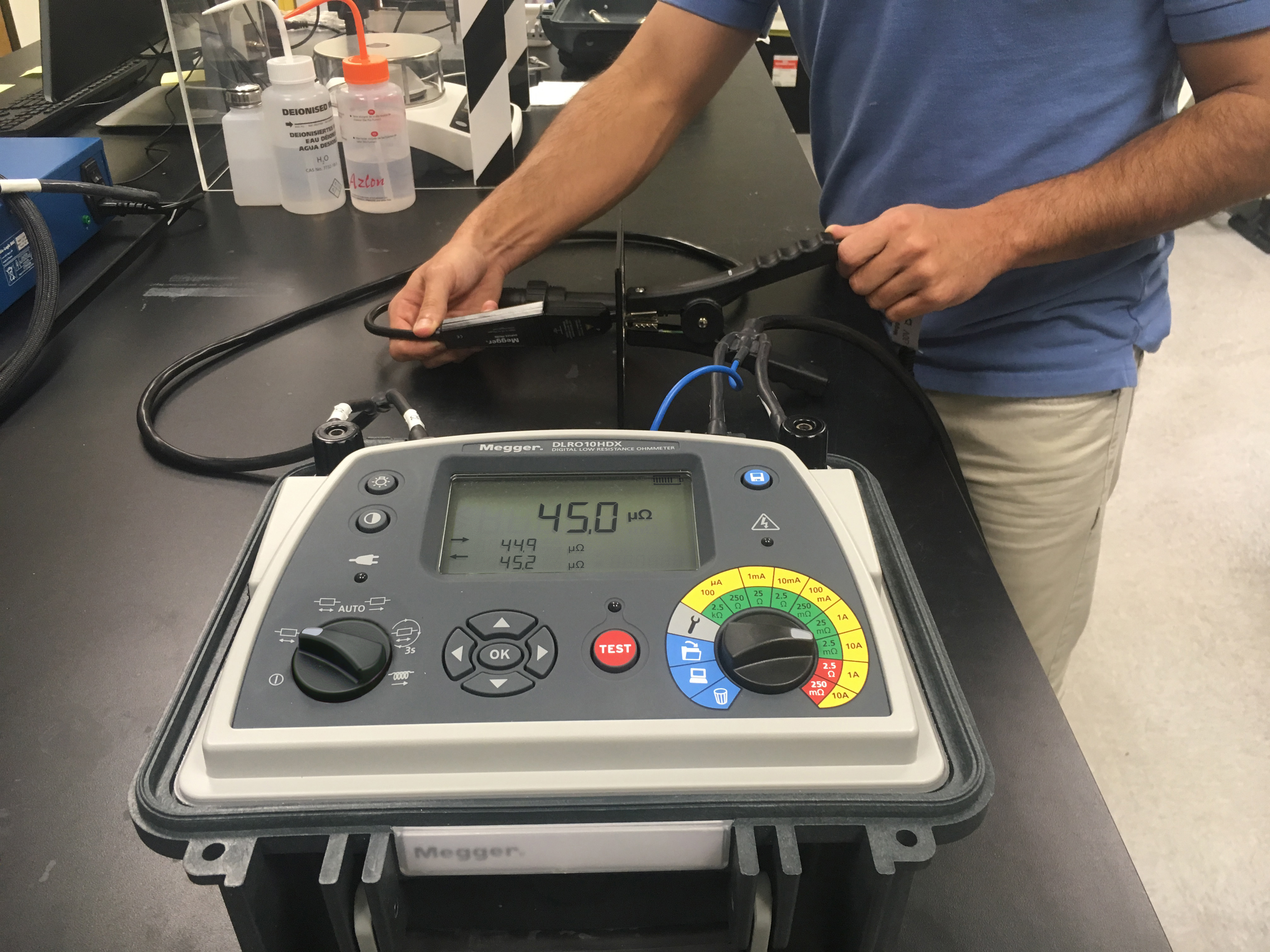
After evaluating several instruments, including ones dedicated for precise scientific research and others designed for routine industrial applications, Gridtential’s technical team chose the DLRO10HDX from Megger. “This instrument offers high accuracy for research and development, as well as the robustness required for daily use on the assembly line where there is repetitive testing,” said Mui.
“We chose this tester because it is capable of delivering 10 A into measurements up to 250 mΩ and 1 A into measurements up to 2.5 Ω, with µΩ resolution and accuracy at both levels. This was important to us because we have various soldered joint designs with different resistances,” Mui continued.
Making the Right Choice
When choosing an ohmmeter, it is important to consider probe selection. This can be just as critical in the testing process as ease-of-use and accurate results, as was the case with Gridtential. High current tests require secure connections to the work surface because high resistance at the contact point can limit the expected level of test current, causing a poor signal-to-noise ratio and ultimately giving erratic results. Use of unsuitable probes for certain applications can lead to unreliable outcomes. The test leads for Gridtential’s application were matched to battery-operated meters to ensure that the nominal level of test current would be delivered to the unit being tested.
“Because our application was somewhat unusual and required a sensitive resistance instrument with special connector options, we needed to be precise in our equipment selection. Ultimately we’re very pleased with the functionality and accuracy of our chosen tester,” said Mui.
Working into the Future
Improving efficiency in testing battery terminal solder joints wasn’t the big picture problem Gridtential set out to solve. However, once it became clear that improper soldering technique or high-resistance electrical contacts could affect the functionality of the product, the company knew that minor detail would be a major consideration during production.
Now, thanks to accurate testing during production, Gridtential’s potential to provide the market with next-generation battery solutions is looking up. The company can focus on developing and enhancing its silicon technology rather than worry about the quality of its batteries. Proper testing with accurate results ensures peace of mind at Gridtential and also assures their customers that they are receiving a reliable, accurate, and functional product.