
Upal Sengupta, Staff Applications Engineer
Texas Instruments
Have you ever had trouble with your car and taken it to the shop for repair, only to have the mechanic tell you that there’s nothing wrong with it? I used to have an old truck that made a weird rattling noise in damp weather. Nobody ever figured out what it was, and the conclusion was that it was supposed to sound that way. (I drove that truck for 15 years before I finally traded it in a few weeks ago, so I guess it must have been fine.)
Sometimes we see the same sort of thing when customers have trouble using battery charger circuits. With the increased use of battery-powered devices nowadays, many engineers who are unfamiliar with battery technology find themselves designing battery charging and battery management for the first time. At first glance, if you look at the typical battery charging IC, it basically looks like it does the same thing as a voltage regulator… you put in some sort of unregulated or semi-regulated DC level, and the output of the “black box” is a precisely regulated voltage and/or current level that is tuned to the specific requirements of the battery that you are using.
While a battery charger does have the same basic characteristics as a voltage regulator, it also has an additional layer of intelligence on top of what the regulator provides. This is necessary in order to maintain the long-term service life of the battery, and also to ensure safe operation under all conditions. The design of a battery charger circuit (whether discrete or integrated) must consider the type of battery and power source that it will be used with.
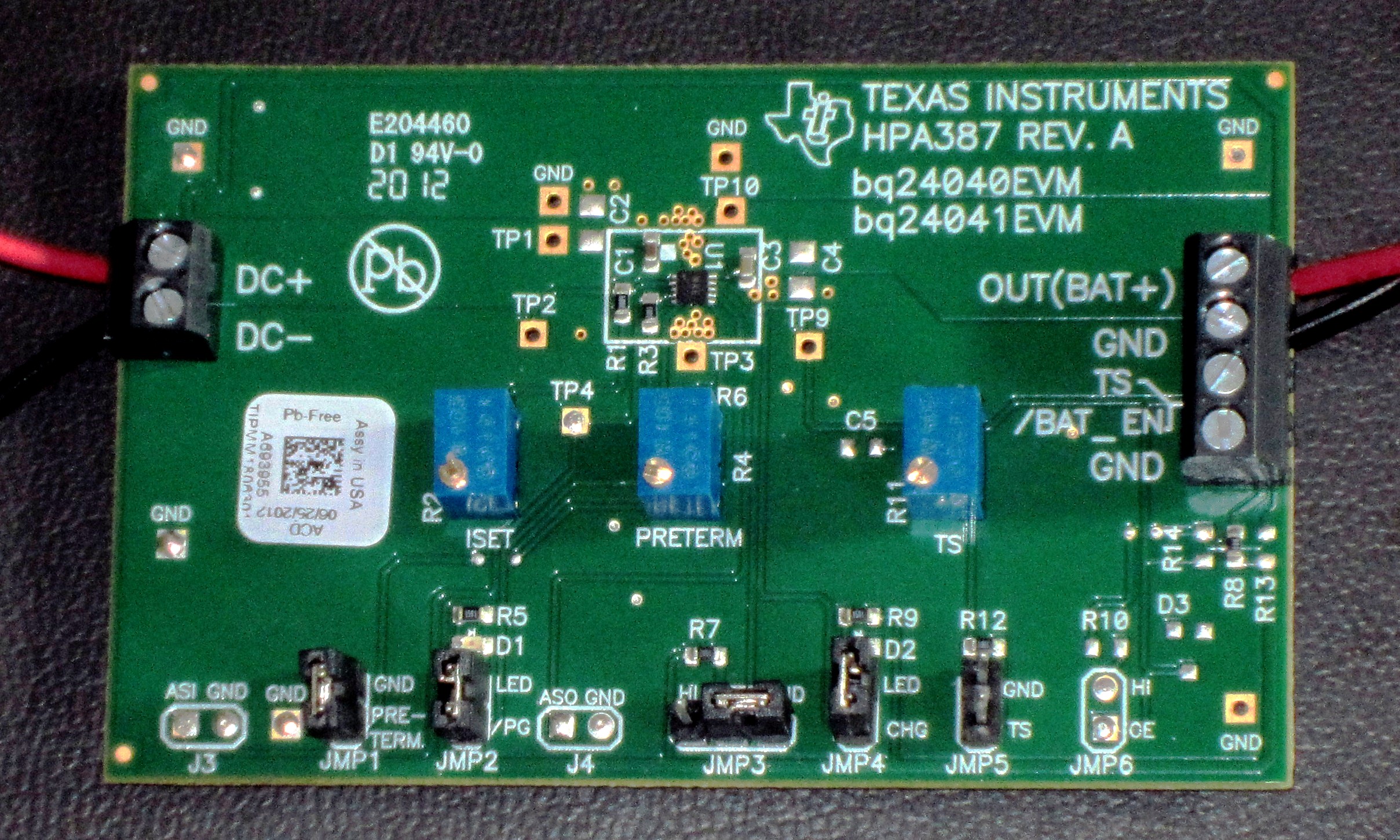
Note that even with simple linear chargers, there are jumper settings and potentiometer adjustments that need to be checked before operating the circuit. The IC Data Sheet and EVM User’s Guide provides details on how these need to be set for proper operation.
In some ways, we can think of a battery charger as a voltage regulator that’s just looking for a reason to shut itself off. If the battery is too hot, we stop charging. If the battery is too cold, we stop charging. If the voltage is too low to safely accept fast charge, we charge slower. If the input source voltage is collapsing (indicating overload conditions), we limit the input current drawn. Of course, these are all necessary features. If you use a “dumb” voltage regulator to charge your battery, you will risk the chance of destroying, or at least degrading, your battery when an unsafe or undesired operating condition occurs.
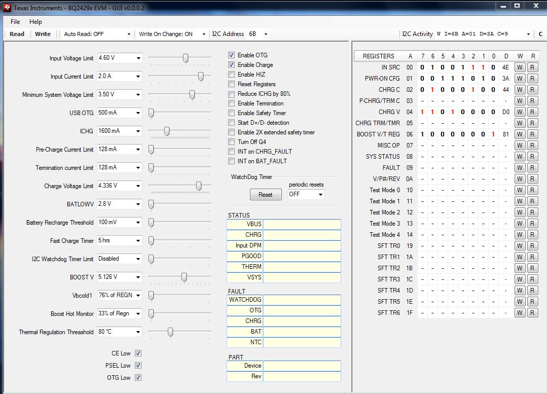
When using a “smart charger” that can be controlled via I2C software commands, software is provided with the EVM to allow control of all programmable parameters. There are many more adjustable values including input DPM threshold, battery fast charge and precharge current, regulation voltage, etc. that all need to be verified before operation of the circuit. These terms and parameters are explained in the IC data sheets and the references provided at the end of this article.
Sometimes, new users of battery charging circuits have trouble with getting things set up, and get frustrated at first because “my battery is not charging.” Often, they may be testing a charging circuit with a dummy load like a resistor or electronic load. If these simulated loads do not properly model the behavior of a real battery, in many cases the charger will think it has detected a fault condition and shut down.
One thing to remember is that a battery is capable of both sinking and sourcing current – so the typical dummy load won’t properly represent this behavior. If you are testing your battery charger, you can build a simple circuit as shown here to mimic the behavior of a battery. The terminals on the left side (marked “BAT”) represent the battery contacts; the terminals on the right (marked “P/S”) are connected to a standard adjustable lab power supply. By connecting the charger circuit output to the BAT terminals, you can now sink current (charger operating), but also maintain a simulated battery output voltage and source current from the lab power source.
Note that R1 and R2 are power resistors with heat sinks. If you are planning to test a high current battery charger, be prepared to dissipate some power. Exercise caution as things can get pretty hot!
Battery charger circuits have many additional characteristics and parameters such as thermal regulation, input dynamic power management (“Input DPM”) thresholds and output power path management that need to be understood in order to optimize your system-level design. So before you think there’s a fundamental problem with your design, check all the operating conditions, along with the source and load that you are using to test your circuit. In many cases, the circuit is just doing what it’s supposed to do. You can learn more about the details of battery charging circuit applications at the links posted in the references.
References
- Understanding battery charging IC Specifications
- Thermal Layout Considerations for Integrated FET Chargers
- NVDC Charging Design Considerations
- Single Cell Charger Considerations
 Upal Sengupta is a staff applications engineer with the TI Battery Management Solutions group. Since joining TI in 2003, Upal has worked as an applications engineer and technical marketing manager in support of TI’s portable power and battery management technology. Prior to TI, he worked as a system design engineer for OEMs developing mobile phones, portable computers, and consumer products. Upal received a BSEE from the University of Illinois, and an MSEE from Michigan State University. Upal can be reached at ti_upalsengupta@list.ti.com.