
Paul Goossens, Vice President, Engineering Solutions
Maplesoft
Demand growth for rechargeable batteries in products such as portable electronic devices, electrified vehicles (EVs) and decentralized power utilities (smart grids) is nothing short of robust. With forecasted annual growth pegged at 8 percent by the Freedonia Group, the global battery market will reach almost $74 billion this year. Rechargeable batteries will account for about 82 percent of that, or $60 billion, according to market researcher Frost & Sullivan.
This strong growth has brought numerous major electronics companies into the market, offering products that target a range of applications: from small and light-weight power for hand-held devices to batteries the size of shipping containers for utilities. It has also led to a significant increase in research investment into battery technologies that address many of the technical challenges facing the industry, ranging from increasing specific energy (capacity of a cell in watt-hours per kilogram, W/Kg), to thermal stability, battery life extension through Battery Management Systems (BMS), and on to final disposal of spent cells.
Technical Challenges in Large Systems
As battery systems get larger, monitoring and controlling them becomes increasingly complex. Issues such as charging and discharging the cell array in a way that minimizes charge times while maximizing energy efficiency and battery life must all be considered when developing Battery Management Systems (BMS) for these products.
In particular, testing the BMS poses major challenges: they are costly to put together, any faults in the BMS design can cause catastrophic damage to very expensive test units, and often it may not be possible to test for all scenarios, such as balancing across the cells, leading to uncertainty around the test results.
An attractive solution to these challenges is to use virtual batteries, mathematical models of battery cells that are capable of displaying the same dynamic behavior as real ones, for early-stage testing of the BMS. Not only have these models proven to be highly accurate, they are computationally efficient and are able to achieve the execution implementation required to deliver real-time performance for batteries containing hundreds of cells on real-time platforms.
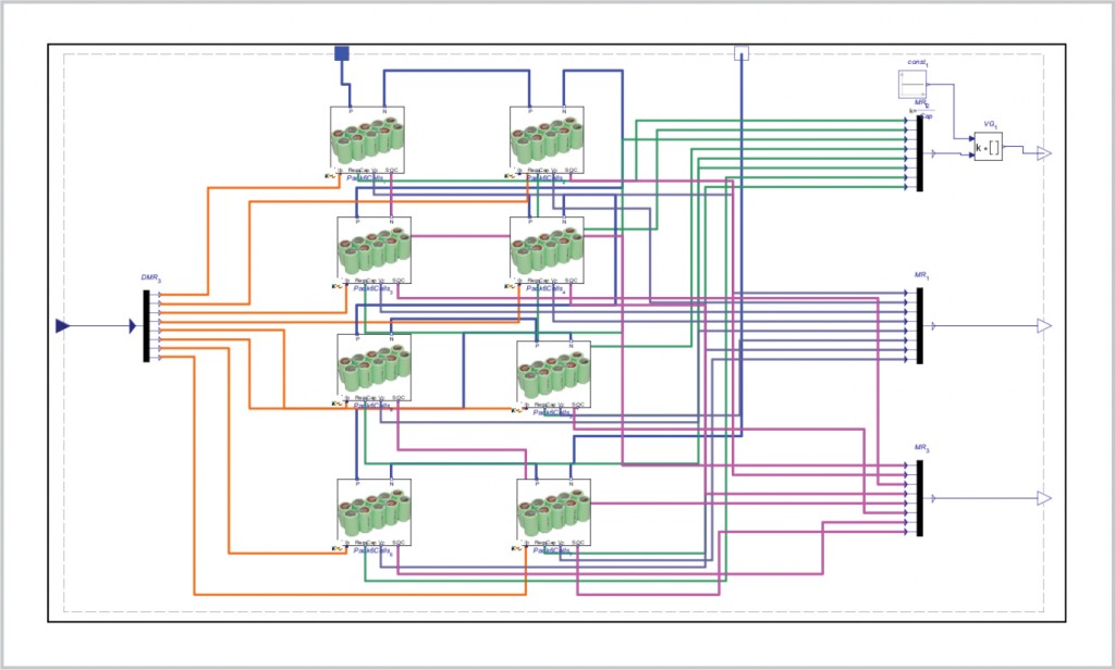
Maplesoft, a developer of battery modeling technology, recently partnered with ControlWorks, Inc. of South Korea to develop a turn-key BMS system for one of the largest producers of consumer electronics products in the world. This project focused on a large electrical storage system for the Smart Grid and UPS markets. The end result was a battery model capable of being configured to represent a stack of up to 144 cells that can be connected in any combination of parallel and series networks. Fault modes were also required, such as individual cells shorting or opening, as well incorporating variations in charge capacity from cell to cell, and degradation of capacity over the life of the cells.
Approaches to Developing High-Fidelity Battery Models
There are two main approaches to battery modeling. The first is to use equivalent electrical circuits that reflect charge capacity and internal resistance through the use of standard electrical components to represent these properties. These equivalent-circuit models are conceptually simple and computationally light, while capable of capturing many of the non-linear behaviors within the cell. However, their scope of operation is somewhat limited and it is not easy to map the components of the model to the physical aspects of the real cell.
The other method is to use electrochemistry-based battery models, those that include the details of the underlying physics within the reaction between the electrodes and electrolytes. These have been shown to be highly accurate predictors of the overall charge/discharge characteristics of a cell. This physical behavior can be represented by a system of well-documented partial differential equations (PDE), such as those developed by Newman. Solving these PDEs, however, can only be achieved through the use of computationally intensive techniques such as finite-element (FE) and computational fluid dynamics (CFD). These approaches make them unsuitable for system-level modeling since they can take hours to compute behavior over a few seconds.
In the last few years a new technique has been developed. This compromise approach provides real-time performance while almost completely maintaining the accuracy of the full physics models. This uses a rigorous PDE discretization technique to simplify the model to a set of ordinary differential equations (ODE) that can be readily solved by system-level tools like MapleSim. The model optimization techniques employed in MapleSim also allow the resulting model code to be fast and capable of running in real-time.
Using these physics-based models, it is possible to implement battery models that predict the charge/discharge rates, state of charge (SoC), heat generation and state of health (SoH) through a wide range of loading cycles within complex, multi-domain system models. This approach provides the performance needed for system-level studies, with minimal loss in model fidelity.
Furthermore, the underlying foundation for model formulation and integration in MapleSim is based on the conservation of energy. Where there are inherent inefficiencies in the model, lost energy is computed as well as the effective (or “useful”) energy. This means that the user can allow for energy loss through heat (in large applications that proportion is very close to 100 percent), making these models useful for performing thermal studies to determine component sizes in cooling systems required to control battery temperature.
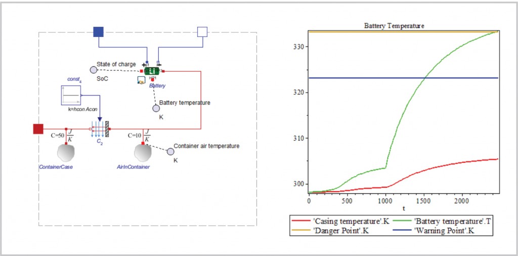
This is critically important when battery SoH must be considered, as the temperature of operation of each cell has a very significant effect on the degradation of its performance. If not carefully controlled, this can lead to reduced operational life or, in extreme cases, destruction through thermal runaway, a common problem in many battery-powered systems. This can be caused by unforeseen loading cycles, or a compromised cooling system compromise. As the battery heats up, its efficiency decreases, causing even more energy loss. Left unchecked, this vicious cycle causes the battery temperature to increase to dangerous levels, ending in failure or, in extreme cases, fire or explosion.
Modeling State of Health (SoH)
Within the MapleSim Battery Library, SoH or capacity fading, during both storage and cycling, is incorporated in both the electrochemical and equivalent circuit models. Studies have shown that the primary cause of capacity fade in the cell is the growth of the Solid Electrolyte Interface (SEI) film between the electrodes and electrolyte. This is caused by the chemical reaction between the two, very similar to corrosion. When the battery is new, the reaction is quite vigorous and an initial SEI forms, slowing down the reaction and protecting the electrode surfaces during battery operation.
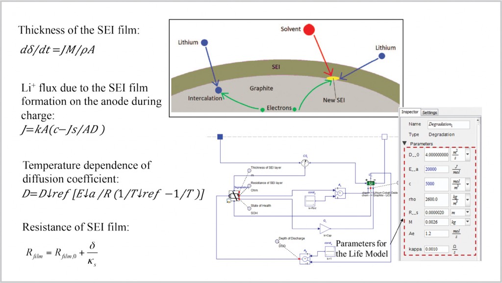
As the battery ages, however, the SEI slowly thickens in a predictable manner, gradually reducing battery capacity and increasing internal resistance throughout its operational life. The formation of the SEI is dependent on several factors, such as the number and the depth of charge/discharge cycles, as well as applied current, time in storage and temperature. These vary considerably depending on the electrode/electrolyte chemistries used. In order to factor the SoH into the battery models, these properties are implemented in the battery library as parameters and look-up tables, depending on the chemistries selected.
Cell Degradation
Cell-Charge Variance and Charge Balancing
A common problem with batteries with large numbers of cells is that all cells are not created equally. Slight variances in cell make-up during manufacture can accelerate degradation of a cell that may have a slightly higher rate of SEI growth than others in the stack. If all the cells are treated the same by the BMS and receive the same charge/discharge demand (current in and out), the depth of discharge (DOD) in one cell may be 80 percent, for example, while in another it is closer to 90 percent. This will cause the SEI growth rate to increase faster in the more deeply discharged cell.
As seen in Figure 4, this will increase the likelihood of that cell failing either through complete loss of charge capacity or, worse, overheating. This is why it is critically important for the BMS to monitor the state of health of each cell and control the current into and out of them in order to balance the charge across all cells.
Development of Cell-Pack Models for Real-Time Applications
For the purpose of this project, the key requirements for the battery model were:
• Up to 144 Li-ion polymer cells for testing the BMS of the client’s ESS products
• Ease of configuration for different requirements (parallel/series networks)
• Several sensors per cell: current, voltage, SoC, SoH
• Implement variation of chemistry make-up due to manufacturing tolerances
• Fault-insertion on each cell: open-circuit, shorting
• Capable of running in real-time (target execution-time budget of 1 ms)
The real-time requirement was the biggest challenge for this project. While the MapleSim physics models are fast, they are not as scalable as the equivalent-circuit model. Therefore, it was decided to use the EC models, with some customized elements from the physics models, for this specific purpose.
Model Structure
In the case of Energy Storage Systems, each ESS battery is made of several “stacks” that, in turn, contain several cells. The model follows this structure with each cell being a shared, fully parameterized subsystem, using the customized equivalent-circuit model described earlier. Additionally, each cell can be switched to open circuit using logical parameters.
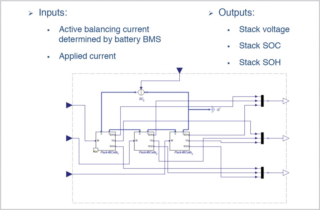
The stack model is made of 18 cell subsystems connected either in parallel or series, depending on the requirement. Input signals are provided for charge balancing from the BMS. Output signals are provided back to the BMS to monitor the condition of the stack: Supply voltage, SoC and SoH.Finally, the full ESS is made of several stacks with IO signals fed to and from the BMS.
Model Calibration and Validation
Much of the accuracy of the model is dependent on experimentally derived parameters, determined from charge/discharge test results. Additionally, any deviation in performance due to manufacturing variations needed to be included in order to test the charge-balancing capability of the BMS. Instead of testing every cell, a smaller batch was tested, from which the average cell response could be determined as well as the statistical distribution of the variants. These were used to implement the manufacturing variability into the cell stack.
The average cell response was determined using the parameter-estimation tool supplied with the MapleSim Battery Library. This uses optimization techniques to determine the values of cell-response parameters that provide the closest “fit” to the experimental results. This response was then validated against response data from other cells to ensure close estimation of the resulting model.
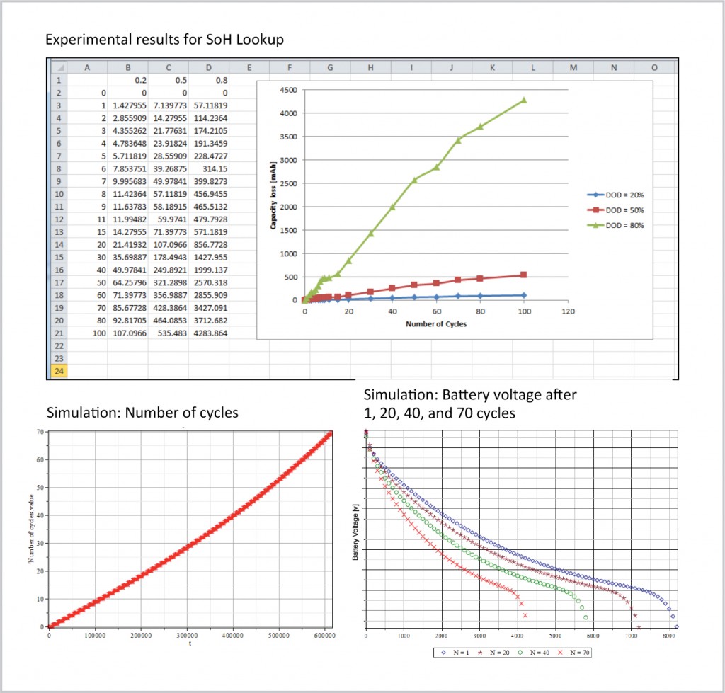
SoH behavior was implemented as a look-up table based on experimental results. The model determines the capacity and internal resistance based on the number of charge/discharge cycles and depth of discharge (DOD) from the lookup.
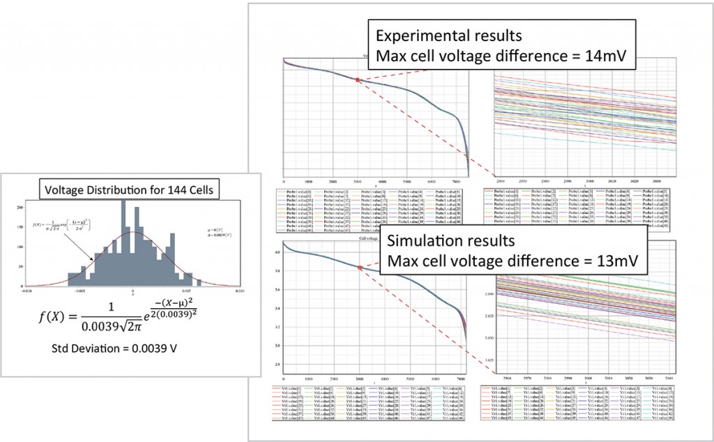
As mentioned, the variation of cell behavior was implemented through the use of random variants, generated from the statistical distribution determined by the charge/discharge results from testing 48 cells. This was applied to all 144 cells and then compared with the real test results.
In Figure 8, we see that the maximum variance of the voltage from the experimental data is 14 mV, while from the simulation it is 13 mV: acceptable for the purpose of this project.
Model-Code Generation and Performance Benchmark
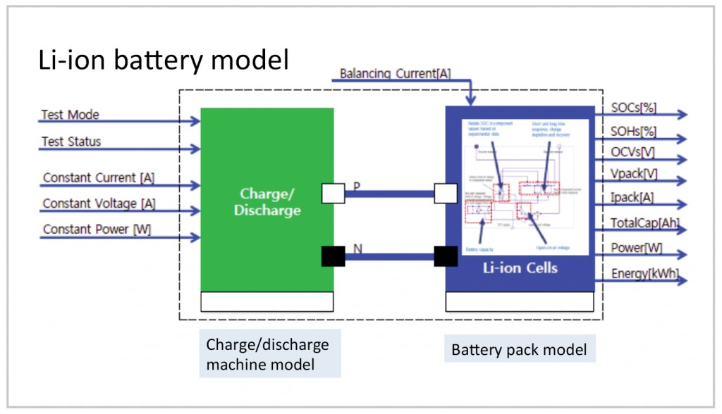
Finally, the model was converted to ANSI-C through the MapleSim Connector for Simulink. This produces an s-Function of the battery model that can be tested for performance and accuracy with a fixed-step solver on a desktop computer in MATLAB/Simulink before moving it to a real-time platform. The simplest solver was used and the performance bench showed that the average execution time was approximately 20 times faster than real-time, occupying 5.5 percent of the real-time system time budget. This shows that the battery model can be easily scaled up, if required. A schematic of the final BMS test system developed for the client is shown in Figure 9.
The testing station provides the engineer with the ability to configure the battery model (number of cells, series/parallel) and apply a range of tests to it. The engineer can go back to the model at any time to make any necessary changes to the model configuration, and then generate the model for use on the real-time platform. In this system, the real-time software was National Instruments’ VeriStand, driving a PXI real-time system. The MapleSim Connector for NI VeriStand Software automates the model integration process, allowing the engineer to produce the real-time model quickly and reliably.
The final ESS BMS Testing System from ControlWorks integrates real-time platform, signal processing, fault-insertion tools and standard communications protocols (CANbus for automotive, Modbus for industrial applications). Software on the operator system includes NI VeriStand, NI TestStand and MapleSim.
The system allows the engineer to run the BMS through a range of tests on the battery model, including Constant Current (CC) and Constant Voltage (CC/CV) charge/discharge cycles, as well as Constant Power (CP) and Constant Resistance (CR) discharge cycles. Results are displayed on the operator console through NI VeriStand and NI TestStand.
Summary
Test automation and simulation is critical in system-level testing. Issues such as time and cost of failure analysis, constant development pressure, costs of repeated tests and lengthy set-up times can all be addressed with improved test systems.
For testing ESS Battery Management Systems (BMS), the use of “virtual” batteries is proving to be an effective alternative to the use of real batteries. They allow the engineer to avoid the risks of damage to the batteries, and subsequent costs, while testing and optimizing the BMS design in a close-to-reality loading environment.
Techniques for battery modeling have advanced significantly over the years to the point where physics-based cell models that would have taken hours to solve in a FE or CFD tool can now be implemented in a system model in order to predict how they would behave under loading from complex multi-domain systems (mechanical, electromechanical, fluids, thermal).
The MapleSim Battery Library provides ready-made physics-based and equivalent-circuit models that deliver the fidelity and performance required for implementation on Hardware-in-the-Loop testing platforms, through MapleSim’s optimized code generation capability. The use of virtual battery technology in the design of test systems can facilitate the development of better products, reduce project risks and get products to market faster.
Simulink is a trademark or registered trademark of The MathWorks, Inc.