
Geoff Shannon, Amada Miyachi America, Inc.
Battery packs have become an integral part of everyday life, powering a growing range of portable electronic devices, cordless power tools, energy storage, and hybrid and electric vehicles. Tab to terminal connection welding is one of the key battery pack manufacturing applications. Manufacturers need equipment, systems, and automated lines that meet quality and production requirements for these products. Both resistance and laser products are well suited to integration into production lines that may be either standalone or automated operation. To maintain the required throughput that offers high quality and yields, users must have a clear understanding of which process is best for the particular battery pack size, tab and terminal material, type, and thickness. In addition, the selected process and integration solution should include process monitoring, process data management, and weld quality assessment.
Battery Pack Basics
Today’s battery packs come in a variety of configurations, as shown in Figure 1.
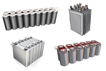
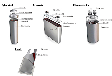
Battery packs use several different battery types, including cylindrical, prismatic, ultra-capacitor, and pouch. Materials joining requirements vary depending on the battery’s specific type, size and capacity. Tab to terminal connections, internal terminal connections, tab welding, seam welding, fill port welding, short circuit protection, laser marking, and external electrical connections are a few key examples. Figure 2 shows the typical joining requirements for the different battery types. This article focuses primarily on welding tabs to terminals.
Battery Pack Manufacturing Systems for Welding Tabs to Terminals
In most cases, pack manufacturers receive individual batteries from vendors, so the critical process step for pack manufacturing is joining the individual batteries together using a collector plate, which consists of tabs for the individual cells to be welded to both the positive and negative terminals. In addition, many packs will need a smaller number of collector plate to busbar connections. Along with considerations of materials, joint geometry, weld access, cycle time and budget, the welding technology selected will also be affected by the manufacturing flow and production. Reviewing all these factors will usually point in the direction of the joining technology most suitable for the application: laser or resistance welding
Fiber Laser Welding
The laser welding process is non-contact, has no consumables, and offers instantaneous welding once the laser is positioned at the weld point location. The weld size and location on the part can be closely controlled and optimized to each application for strength and conductivity. There are number of motion options that can be tailored to each manufacturing environment.
For tab to terminal welds, fiber lasers can be used for prismatic, cylindrical and pouch battery types, as well as ultra-capacitors. The tab thickness can vary from 0.006-0.08-inch for both aluminum and copper tab material, depending on the size of the battery. The fiber laser is able to weld many material combinations including aluminum to aluminum, aluminum to steel, copper to steel, and copper to aluminum. Whatever the material combination and part thickness, the laser must not penetrate the can or overheat the battery. Suitable selection of the fiber laser, spot size, weld parameters selection and controlling the weld path enables fine control of both penetration and heat into the part.
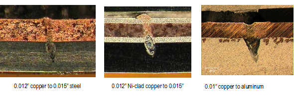
Figure 3 shows some examples of common dissimilar materials combinations for tab to terminal welding. For a lap weld the tab thickness should be ideally 50 percent thicker than the can thickness. This provides a large processing window and high production yields.
The fiber laser source can be sized and matched with the appropriate motion platform according to cycle time and production throughput. For high volume systems, the welding time can run at < 100 milliseconds (ms) per weld, while low volume production systems run at about 1-2 seconds per weld.
Resistance Welding
Resistance welding has been used in the battery industry for 40 years. A steady stream of advances in resistance welding systems has given users significantly improved capabilities to control various aspects of the process. For example, the introduction of DC inverter power supplies with basic closed-loop electrical modes provides the ability to accommodate changes in the secondary circuit (the electrical loop from cable connection on the negative side of the power supply or transformer, through the weld head and the parts returning to the positive side) to specifically address part resistance. Also, polarity switching for capacitance discharge supplies to enable balancing of the weld nuggets, and more recently, the addition of displacement and electrode force measurement, provide manufacturers with more tools to ensure weld quality.
Resistance welding is the most cost-effective method for joining tabs on a wide range of battery types and sizes, using both DC inverter closed loop and capacitor discharge power supplies. With fast rise times, closed loop feedback control, polarity switching, and options for displacement and force sensing, the process can be finely tuned and monitored to ensure both high quality and yield.
For nickel tab thicknesses up to 0.0070-inch, the tab can be welded without modification. Beyond this thickness, and to prevent electrical shunting and excessive electrode wear, a slot and projections are placed in the tab as part of the stamping process. The projections act not only as energy concentrators for the weld, but also greatly increase electrode lifetimes.
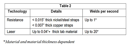
The important aspects of tab welding for battery packs are the thickness and material of both the tab and the terminal. Resistance welding is extremely well suited to welding nickel tab material up to 0.015-inch thickness, and nickel or steel clad copper tab material to around 0.012-inch thickness to a wide variety of terminal materials. Welding tabs or terminal connections to buss bars generally does not require as much penetration of heat input control as the tab to terminal welds. The materials, material thickness and combination of materials determine the best welding technique.
Understanding Which Technology to Select for Battery Pack Manufacturing
Battery pack production volumes are driven by the demands of consumer electronics and electric vehicles. Likewise, the manufacturing and joining needs are determined by the pack size, type and thickness of the busbar, and tab and terminal materials. Laser and resistance technologies each have specific features that align well to these joining needs. A clear understanding of the technologies and application is needed to implement an efficient and reliable production battery pack welding system.
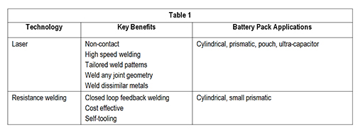
Table 1 offers some guidelines on the available methods and a few parameters, including suitability for a variety of battery pack applications. Table 2 provides an overview of battery pack joining applications and key components of joining solutions required.
System Solutions for Battery Pack Manufacturing
A complete production solution for battery pack manufacturing needs to deliver and support the required product flow. The system must take into consideration how the pack is loaded and unloaded, how the un-welded parts are held prior and during welding, and whether and to what level the system reports data and information to the supervisory control software.
Enclosures
The enclosure requirements for laser and resistance welding are quite different; the key difference is the need for lasers to be housed in a class 1 light-tight enclosure according to ANSI 136.1. This requires the complete system be enclosed, and adds the need for enclosure doors for part load and unload in addition to access panels for setup and maintenance. For a resistance welding system, although there may not be any panels, light curtains are used to protect the keep out zones. If loading into the enclosure is automated, a conveyer is commonly used.
Motion
To support in line production that uses conveyers, and to minimize the system’s physical footprint, resistance weld heads or laser focus heads should be moved, while the pack remains stationary. For resistance welding systems, a defining factor in determining whether the weld head or pack moves is the length of weld cables needed. Increasing the length of the weld cable requires additional voltage from the power supply to push the current through. This tends to limit cable length to between three and eight feet, depending on the application and power supply.
Scan heads are being used for more and more laser welding motion solutions. For low volume applications, scan heads offer cost effective solutions. For high volumes, scan heads offer a very high speed motion that can be utilized to minimize weld times and point to point positioning times. Scan heads can also provide a large weld area, with certain configurations providing up to and greater than a 10×10-inch (250×250 millimeter) weld area. For large pack sizes this minimizes the number of steps needed to weld the entire pack, which can significantly reduce cycle time. For example, the point to point positioning of the scan heads for a 1-inch (25mm) travel distance can be completed in 10-20 milliseconds.
Tooling (for Laser Welding Only)
The ease of tooling a material is directly related to the tab or busbar thickness and subsequent stiffness. Thick material with high stiffness does not deflect under clamping pressure, so it maintains contact with fairly simply tooling. However, as the tab thickness for many battery packs is less than 0.015-inches, this means the tab stiffness is not sufficient for simply clamping. Instead, it requires a well-designed tool to apply a localized clamp force that ensures intimate contact, but does not damage the parts.
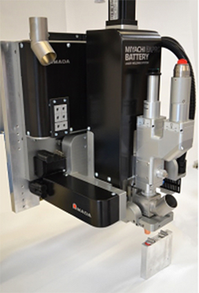
With decreasing tab thickness, tooling becomes even more critical. Welding a tab thickness of less than 0.005-inches (0.125mm) is not recommended. Another critical factor for laser welding tooling and part positioning is ensuring the part’s weld surface typically in the z or vertical plane is maintained to the laser’s focal position. This sometimes requires the use of height sensors or vision systems. Shown in Figure 4 is an example of a laser welding focus head with integrated tooling.
Communication
The protocol and control of data to and from a system depends upon the level of automation and the manufacturing environment. Therefore, options and a flexible platform for communication control software and data management are needed to ensure scalable functionality and performance in diverse applications. For example, Smart Factory and Industry 4.0 industry initiatives demand data transmission speed, networking, storage capacity, and processing power that are far greater than traditional use cases for such methods as Statistical Process Control and machine monitoring. To meet these needs, modern battery assembly systems are equipped with protocols such as EthernetIP, PROFINET, and Modbus TCP/IP. These Ethernet-based protocols offer ready-made solutions for network configurability, ease of integration, unparalleled data transmission speed and security, and the ubiquitous availability of network hardware and software.
Process Monitoring
Even after optimizing a process, there are certain production tolerances and setup factors that will cause a weld defect. For laser welding, the key factors are part fit-up and maintaining the focus of the laser at the part weld interface. For resistance welding, electrode wear is the key culprit.
There is a comprehensive range of resistance welding process monitoring products that provide information independent of the power supply or weld head regarding variances in the weld electrical properties, force and displacement. For example, one can monitor the weld’s dynamic resistance, voltage or current over the duration of the weld pulse. In addition, one can measure the rate of the weld collapse as well as the overall weld collapse. All this information can be used for process monitoring. At present, data is collected, a set of waveforms defined, and then limits or an envelope is placed around the waveform. Future technologies will likely offer better tools to define the good weld/bad weld decision, as well as provide predictive analysis.
Monitoring laser welding is more challenging, because it is a non-contact process without the benefit of electrodes touching. Typically, monitoring techniques capture certain wavelengths of light from the weld area that correspond to ultraviolet from the welding plume and keyhole, infrared from thermal heating of the part, and the back reflection of the laser light itself. With suitable sensing and analysis, these signals can be utilized as a basis for process monitoring.
Amada Miyachi America offers a complete range of resistance welding power supplies and lasers specifically designed for both low and high volume battery pack manufacturing.
Technologies are matched to production needs as either standalone products or fully integrated system solutions. Solutions can be adapted to accommodate welding of dissimilar metals for battery tabs and tab design optimization. An optimized software application, developed in Amada Miyachi America laboratories, is delivered with each system.
For more information visit Amada Miyachi.