
James Niemann, Analog Design Engineer, Tektronix
One of the demonstrations we often set up at battery conferences is to use a source measure unit (SMU) to measure the internal resistance of an energy storage device such as a battery or a fuel cell. In such demonstrations, the SMU changes the load current from the battery operating current or the polarizing current to the open circuit potential and simultaneously measures the change in cell voltage. In this “current interrupt method,” the battery’s internal resistance is equal to the change in voltage divided by the change in current.
The demonstration is popular among battery engineers because it shows how battery internal resistance can be measured at large polarization currents using a cost-effective SMU, a type of instrument capable of sourcing and measuring voltage and current at the same time.
This is a difficult measurement that even a much more expensive electrochemical impedance spectroscopy (EIS) instrument cannot accomplish at high current levels. Historically, electrochemists have used an oscilloscope and a switch (for the load) to perform these measurements, and have achieved what’s best termed a figure of merit rather than the real internal resistance.
Let’s look at how we are able to achieve verifiably accurate measurements using an SMU. The key here is to pay close attention to several non-obvious details.
Complex Impedance
Battery internal resistance is a measurement of the real part of the complex impedance of the cell. Figure 1 shows a simple electrical model of this complex impedance known as the Randles circuit model.
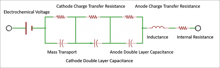
In the Randles model, each electrode redox reaction is modeled with a resistor and a capacitor representing the charge transfer resistance and the double layer capacitance for the electrode respectively.
- The charge transfer resistance represents the activation energy required to drive the intended electrode reaction forward at a specific rate.
- The double layer capacitance is a measure of the slowness of the electrode reaction resulting from charges building up on each side of the electrode, again at that same specific rate.
- Rint is the real component of the impedance of the cell.
For most cells, the supporting electrolyte (an ionic conductor) is the source of most internal resistance. Electrodes and external interconnection resistances are usually much smaller contributors. Current flow generates heat, which may have an impact on internal resistance measurements and should be taken into consideration.
Elevated internal resistance measurements can be a sign that a cell is nearing failure since electrolyte resistance tends to increase as cells age. While resistance can increase for a variety of other reasons as well depending the chemistry of the cell, measuring internal resistance characteristics can be a useful indication of the overall health of an electrochemical cell, particularly when evaluated over time.
Internal resistance measurements are also useful for evaluating whether a battery can deliver its stored energy effectively. In general, a battery with low internal resistance is better able to deliver high current on demand. High resistance causes the battery to heat up excessively and voltage output to drop under high demand. This is especially important for heavy loads such as power tools and electric powertrains.
The Current Interrupt Method
To understand how to use the current interrupt method to measure the real part of the complex impedance, refer back to the Randles circuit model in Figure 1. In the model, the geometrical inductance of the cell and the test instrumentation interconnects are shown along with the electrode parameters previously discussed.
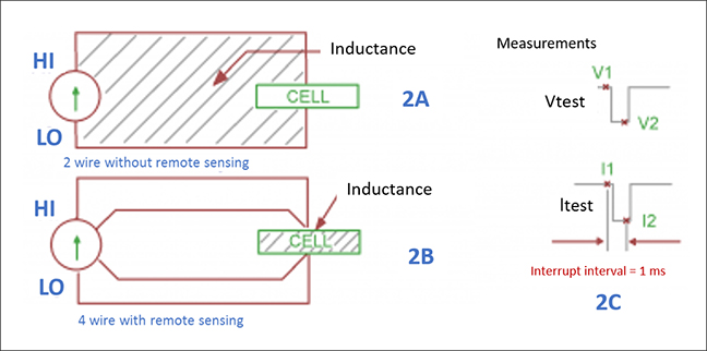
If this measurement is set-up without remote sensing enabled, the inductance shown in the model will be the total inductance of the measurement loop a shown in the 2A portion of Figure 2. With remote sensing enabled, only the inductance of the cell itself is measured as shown in 2B, only the impedance between the sensing leads is being measured, complex or not.
When an SMU is set up to source voltage in the remote sense (4-wire) configuration, external sensing provides a feedback voltage that is measured and compared to the programmed level. The voltage source is adjusted until the feedback voltage equals the programmed voltage level. Remote sensing compensates for the voltage drop in the test leads (and analyte in the case of an electrochemical cell), ensuring the programmed voltage level is delivered to the working electrode.
To measure Rint, the interrupt or change in the cell current needs to be measured for just the right amount of time so that the reactance’s sum is zero, thus leaving only the measurement of the real part of the internal resistance as shown in 2C. In general, there is only one interrupt delay that can satisfy this requirement for any given cell and measurement geometry. Interrupt intervals can vary from 80 microseconds to several milliseconds depending on the size and configuration of the cell.
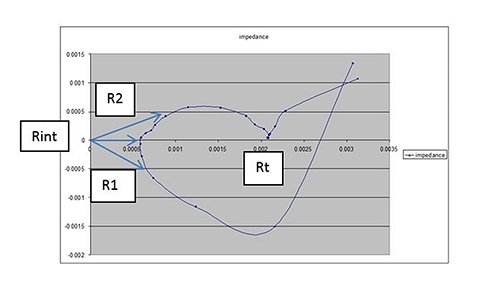
To properly measure the internal resistance of an electrochemical cell, it is common to run an EIS plot or to measure the complex impedance of the cell over the operating range of cell currents. The internal resistance is the point on the curve where the complex impedance crosses the real axis, or when the reactive components sum to zero.
The current interrupt method of measuring Rint imparts a scalar measurement, representing the magnitude of the impedance vectors shown superimposed on the complex impedance plot shown in Figure 3. The correct interrupt time can be easily found by varying the interrupt delay to minimize the vector magnitude, shown as Rint in Figure 3. The other vectors, R1 and R2, obtained by changing the interrupt interval, show larger magnitudes. Note that the second x axis crossing is not the battery internal resistance but rather the sum of all resistances in the model from Figure 1. This point is shown as Rt in Figure 3.
SMUs for Open Circuit Potential Measurements
Using this short concise method will consistently deliver correct internal resistance measurements for batteries and electrochemical cells. SMUs are well suited to open circuit potential measurements on electrochemical cells since they require instruments with high input impedance, which the SMU provides. When paired with electrochemistry test scripts, SMUs are fully capable of operating as a galvanosat or potentiostat, and can measure the internal resistance of batteries, fuel cells, or any electrochemical cell while providing the polarization current.
James Niemann is an analog design engineer for Tektronix. He has worked in the Keithley Instruments division in Cleveland, Ohio since 1988. He is currently a principle design engineer responsible for general R&D as well as the design of new products used for electrochemical research.