Upal Sengupta, Staff Applications Engineer
Texas Instruments – Battery Management Solutions
One (almost literal) “rule of thumb,” which I learned some years ago, was that if you couldn’t hold your finger on an IC for more than one second without feeling pain, the chip’s case temperature was probably above 50ºC. While I don’t recommend this technique as a substitute for doing actual thermal measurements on your PCB, it was an interesting discovery at the time… and of course it was also easier to do when IC packages were a little bigger than they are now.
 Anyone who works in the area of power conversion and/or battery management electronics knows that efficiency is important. What the end-user of a portable product experiences in terms of efficiency is the battery life and the surface temperature of the device. (Anyone who has made a long voice call on a mobile phone without using a headset probably knows what I am talking about). And while someone may not notice a 5 percent or 10 percent difference in battery life over a period of several hours, they could certainly sense an additional 5 or 10 degrees of heat on the outer surface of their handheld device. While IC die temperatures can be pushed above 100ºC according to most data sheet specs, we have to remember that in the case of handheld products, we may be restricted to even lower temperatures – not because of silicon limitations, but because the product may feel too hot for the user to hold. Given the increasing power density and tight packaging of handheld products, the heat generated on a PC board often finds its way to the exterior case of the device.
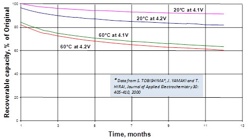
We also know that high temperature is one of the primary factors in battery degradation. For products with embedded battery packs, the cells will be close to the (heat-generating) electronics, so keeping the PCB cool is essential to prolonging battery run-time as well as service life. Figure 1 below shows the accelerated (permanent) loss of usable capacity for a lithium-ion battery when exposed to high ambient temperatures over extended time periods.

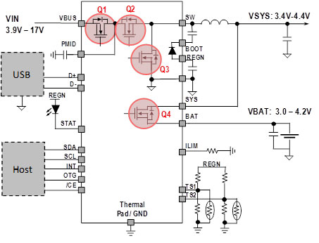
Considering that most higher-current (> 1A) chargers in portable electronics already use switch-mode topologies for enhanced efficiency, what can we do to minimize losses in the power converter? There are numerous sources of loss in any switch-mode power supply, such as inductor core and winding losses, along with power MOSFET conduction and switching losses. The calculation of those loss terms can be quite involved, and is explained in more detail in Reference 1. But without doing any calculations at all, it should be apparent from the example shown in Figure 2 that minimizing the on-resistance (RDS_ON) of the power MOSFETs in the switch-mode charger will reduce conduction losses. This type of loss is a major contributor to heat generation, especially in high-duty cycle applications. Charging a 3.0 to 4.2 V lithium-ion battery from a 5 V power source corresponds to this use case.

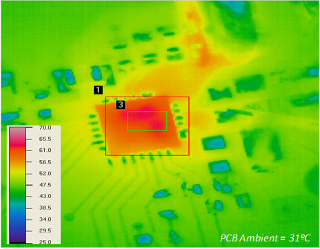
Of course, one may use the largest possible FETs to give the lowest possible RDS_ON and least heat generated, but we need to find a practical balance point between efficiency, size, and cost. In the case of the bq24190 device, the RDS_ON values for Q1, Q2, and Q3 are in the range of 25 to 30 milliohms typical and Q4 is even lower, at 12 milliohms. Q4 is optimized to allow for longest possible run-time when operating only from the battery. Figure 3 shows a thermal image of a bq24190 charging a battery at 4A current, using a 9 V input supply and a 3.8 V battery voltage at an ambient temperature of 31ºC. The thermal rise is only about 30ºC above ambient under this high current load condition.

So, it seems like the best way to keep your cool is, indeed, to follow the path of least resistance.
References:
- Jinrong Qian and Lingyin Zhao, Texas Instruments 2006 Portable Power Seminar, Topic 5: Circuit Design and Power Loss Analysis of a Synchronous Switching Charger with Integrated MOSFETs for Li-Ion Batteries, http://focus.ti.com/download/trng/docs/seminar
- Texas Instruments, bq24190 data sheet, 2012: http://www.ti.com/product/bq24190
- Charles Mauney, “Dynamic Power-Path Management and Dynamic Power Management,” 2007. http://www.ti.com/lit/an/slua400/slua400.pdf
- Wang Li, “A Discrete Narrow Voltage DC/DC Charger Solution for Multicell Batteries,” 2011. http://www.ti.com/lit/an/slua620/slua620.pdf
 Upal Sengupta is a staff applications engineer with the TI Battery Management Solutions group. Since joining TI in 2003, Upal has worked as an applications engineer and technical marketing manager in support of TI’s portable power and battery management technology. Prior to TI, he worked as a system design engineer for OEMs developing mobile phones, portable computers, and consumer products. Upal received a BSEE from the University of Illinois, and an MSEE from Michigan State University. Upal can be reached at ti_upalsengupta@list.ti.com.


