
Jörg Sauer, Senior Applications Engineer Modeling • dSPACE GmbH
Friedrich Hust, Research Assistant • RWTH Aachen University
Fabian Frie, Research Assistant • RWTH Aachen University
The storage system used in electric vehicles (EVs) and hybrid electric vehicles (HEVs) is a key component of the drivetrain and defines the vehicle’s performance. To tap the complete potential of storage systems, it must be possible to model, simulate and test them holistically and seamlessly.
Developers of energy storage systems have to keep many different aspects and requirements in mind. Different thermal and electric factors have to be observed. The battery technology is just as important as the geometric shape, number and allocation of the storage cells. Developers also have to be aware of the temperature behavior, including the peripheral cooling system.
In order to evaluate the overall system, engineers have to observe the thermal and electric effects at cell and system level and analyze the interplay of the individual cells with the peripheral cooling system, electrical system, housing and battery management. This is possible only if the system is embedded in the vehicle environment.
The efficient development of storage systems and their design and integration in the vehicle, therefore, requires a seamless simulation-based environment that lets developers model, simulate and test the overall system. The models have to be real-time-capable so that the storage system can be integrated in the vehicle and tested together with the battery management system (BMS).
The simulation-based Toolbox Energy Storage Systems environment supports the entire model-based development process of energy storage systems for electric powertrains. A detailed battery model was developed, which is used for system design and model-based BMS function development. If the real BMS is available, it can be tested on a hardware-in-the-loop (HIL) test bench that simulates the real-time-capable battery model. The model’s parameterization defines the accuracy and level of detail of the battery model, enabling a seamless simulation and test environment.
The work presented in this paper is the result of the Toolbox Energy Storage Systems project funded by the state of North Rhine-Westphalia and the EU.
Storage System Model
The Institute for Power Electronics and Electrical Drives (ISEA) of RWTH Aachen University developed a modeling framework for storage systems, which lets users simulate the electrical and thermal behavior of batteries in any sensible circuit (parallel or series). Batteries are strongly nonlinear systems that depend on the current operating point (especially on the state of charge, temperature, aging, and electrical load).
Electrical
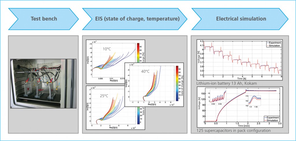
The battery’s electrical behavior can be approximated by an electrical equivalent circuit diagram whose elements change according to the operating point. To make the model as accurate as possible, special measurement tools and methods are used, such as electrochemical impedance spectroscopy (EIS) and relaxation measurement. ISEA has long-standing experience in battery parameterization and has already developed its own hardware solutions for various measurement methods. For example, the EISmeter, a laboratory measurement device for impedance spectroscopy in batteries, was developed at ISEA, brought to production quality by the Digatron company, and is now on the market.
The batteries are analyzed in the on-site test center, where they are measured in special climate chambers under controlled and reproducible environment conditions. The measurement data is entered into look-up tables in the model. Figure 1 shows a typical workflow for the electrical parameterization of a battery. The individual impedance ranges at different states of charge (SOC) and different temperatures are measured and then combined to form an electrical model. Models that are parameterized in this way emulates the current-voltage relation very accurately but are also very CPU-intensive. To be suitable for HIL simulation anyway, these models use systematic and mathematic model reduction processes, which allow for faster computing.
Thermal
The second important element, in addition to the electrical component, is the thermal modeling and simulation. This simulation receives the dissipated heat calculated by the electrical simulation and uses it to calculate the temperature distribution in the battery or battery pack. The temperature distribution is fed back to the electrical model via look-up tables of the electric components, as described above.
For determining the temperature curve within a cell, it is important to keep in mind that the heat conductivities are anisotropic due to the winding and layer structure in the individual battery cells. The cells can conduct heat to the metal deflectors well, but the conduction resistance orthogonally to the different layers is high. ISEA has developed and tested measurement methods for determining the anisotropic conductivity. The measurement results are used as input parameters for the thermal model.
The mathematical structure of the model is based on the finite volume method. The discretized model is made up of individual elements that are derived from various marketed battery types. The users can therefore use preconfigured blocks for prismatic, cylindrical cells and pouch cells. The individual blocks can be variably spatially discretized via an XML configuration file and combined to model the entire battery pack. Not only the cell distribution but also the core variants can be specified by setting the appropriate framework conditions.
The coupled thermal-electrical model can be simulated both on real-time hardware and offline. The results of the thermal simulation on the real-time hardware can be used to test BMS that have thermal management in addition to electronic monitoring. Thermal monitoring is particularly important for lithium-ion batteries to avoid a thermal runaway, for example. For the simulation, this means that the real-time hardware outputs individual temperature values of certain positions within the battery pack. These positions represent the locations of the planned temperature sensors.
But the simulation software can be used for more than just testing the BMS on the real-time hardware. It can also be used while building and designing the battery pack to identify potential hot spots that could occur when using the battery pack. The simulation results can furthermore be used to determine how many temperature sensors have to be installed in the battery pack and where.
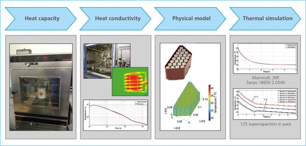
Figure 2 displays the basic process of thermal modeling and simulation, from defining the thermal parameters to validating the simulation results. First, the heat capacity and anisotropic heat conductivity of a specific storage system are determined. Then, an XML file is used to emulate the system (e.g., a cell, a module or a battery pack). The XML file also contains all starting and framework conditions, such as the initial system or environment temperature and data on cooling systems, if applicable. The defined scenario can then be simulated and afterwards validated by using real measurement data.
Graphical User Interface for Parameterization
The electrical behavior is defined by the battery topology, which emulated the battery network, and the model parameters for parameterizing the equivalent circuit diagram that were derived from the impedance spectroscopy. The thermal model is specified using the geometry and the parameters generated from the thermal measurements. Therefore, the model description and parameterization are very detailed and complex and offer a highly precise simulation of the physical processes in the battery.
Because this model requires expert know-how, there is a second, simpler way to parameterize the model. Here, the model structures for certain technologies and geometric topologies are already provided. A graphical user interface (GUI) lets developers display the simplified thermal and electrical model structures in a meaningful way. This means that especially users without expert know-how can parameterize the battery model for their applications in order to perform simulation for designing the battery or testing the battery management.
Intuitive GUIs are provided. These GUIs describe factors like the geometric dimensions and thermal material parameters of the cell. By using a discretization factor, users can define the spatial dimensions (discretizing the cube in finite volumes), thus defining simulation accuracy.
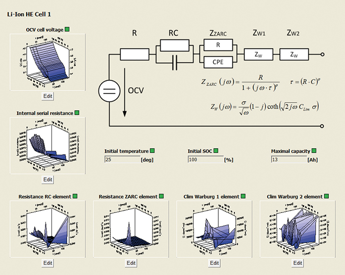
Figure 3 shows how the electrical properties of the cell are displayed in the GUI as an equivalent circuit diagram in addition to the thermal properties.
In addition to the electrical and thermal properties at cell level, the overall battery topology must be specified. To do this, users have to define the electrical wiring and spatial orientation of the cells. As illustrated in Figure 4, users can specify how the cells are wired in parallel or in series and how they are spatially distributed.
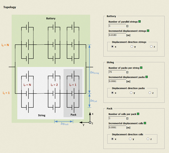
The number and positions of the various elements completes the description of the battery topology. Because battery malfunctions also have to be simulated, users can define an additional cell with different parameters, such as a different initial SOC. Users can then include this cell in the overall battery topology. This lets them simulate effects for testing cell balancing.
There are also GUIs for describing the housing and peripheral cooling system. Additionally, the parameterization environment can also be used to manage many parameter sets for various models and download them to offline or online simulations.
Summary
The simulation-based Toolbox Energy Storage Systems environment lets users model, simulate, and test a complete energy storage system both on real-time hardware and offline. The storage model emulates the electrical and thermal behavior and the interplay of the individual cells with the peripheral cooling system, electric system, housing, and battery management system.
A very detailed and complex model description and parameterization is already provided. A graphical user interface (GUI) for intuitive parameterization enables users without expert know-how to use the battery model for their applications. All this makes it possible to seamlessly support and accompany the development process of an energy storage system.
For more information, contact dSPACE at www.dspace.com.